

Crimping Connectors and Mounting the Switch
A Woodturner’s Crimping-
Connectors that are crimped onto the conductor are reliable and easy to install. However, a crimping tool is required and not everyone has one of these lying around. The tool is fairly expensive and there may be some reluctance to purchase a tool that may be used for only one project.

The first thought may be to use a pair of pliers to crimp the connectors. Not a bad idea, but it doesn’t work. You can’t supply enough concentrated force to do the job. But I’ve discovered a method that will work, and it’s surprisingly easy.
Here’s what you need: a lathe, a faceplate, a hammer, and a 20-
The idea is to place the connector, with the wire in place, on the ways of your lathe, held there, in part, by the weight of the faceplate. Place the nail crossways where the crimping force needs to be applied, then hit the nail one good lick with the hammer. Job done. Instant crimp.


Now, on to some details.
Stripping the wire. The use of wire strippers is preferred by a wide margin, but you can use a pocket knife (or a box cutter) if you are careful not to cut through the insulation and into the wire. If you are stripping stranded wire, like a lamp cord, no strands should come away with the insulation. If some of the strands are cut, chances are that many more are at least nicked, and they will break in short order. Then, your connector will simply fall off.
Size matters. It is important to have the right size connector for the wire. You may not get a good crimp if the connector is too large. A package of connectors will state the range of wire sizes for which the connectors are suited.
Test the crimp by pulling on it. If you can pull the wire out of the connector with a modest force, you didn’t hit it hard enough. Of course, if you pull really hard, the wire will break, but this is not the same as having the wire pull through the crimp.
The size of the nail. The diameter of a 20-
Hard surface required. The ways of the lathe provide an ideal surface for doing
this low-
Placing the connector on a block of wood, even a hardwood, is not likely to work. You will get insufficient compression at the crimp, and the connector will be deformed at the same time. You wind up with a bent connector and a crimp that’s no good.
Practice by making a few crimped connections before you try it for real.
B utt Splice. If the switch you select has wire leads rather than screw terminals
or spade lugs, you can use butt-
utt Splice. If the switch you select has wire leads rather than screw terminals
or spade lugs, you can use butt-
Mounting a Remote Switch
The first thing to do is figure where you want the switch to be, then figure out a way to put it there. The location of a switch that is not “portable” dictates whether the switch should be completely enclosed or possibly left open on the back. If the switch is located where shavings are likely to fall, a full enclosure is in order.
If your preference is to have a portable switch, the emphasis shifts to the enclosure. It should enclose the switch completely and be sturdy enough to withstand being dropped from time to time.
Dry wood is an excellent insulator and I think ideal for making switch enclosures,
which basically amount to wooden boxes. The method I use is to glue the sides onto
a base made of 1/4” plywood (or 7/32” paneling). Then, if the enclosure is for an
ordinary light switch, I’ll use a standard switch cover if the enclosure is full
size, or make one if it’s not.
switch enclosures,
which basically amount to wooden boxes. The method I use is to glue the sides onto
a base made of 1/4” plywood (or 7/32” paneling). Then, if the enclosure is for an
ordinary light switch, I’ll use a standard switch cover if the enclosure is full
size, or make one if it’s not.
An enclosure for a toggle switch can be a much simpler affair. The following shows one made from a 2x2 (1.5 x 1.5”, actual) by drilling three holes and adding a plywood base.


When making the enclosure, drill the 7/16” hole first, drilling into the “handle side.” It’s only necessary to drill to a depth of about 1/4”. Then turn the piece over and drill the 3/4” hole to a depth of about 1/2”. Finally, drill the larger hole. When you get near the desired depth, stop frequently and check the depth, looking through the 7/16” hole you drilled first. Forstner bits are good in this application.
The following diagrams show various possibilities.


Magnets, Velcro, and Double-
A lot of turners like to attach magnets (with epoxy) to the enclosure so the remote switch can be stuck to the lathe almost anywhere. I tried this, and my results were marginal, at best. First, I used two magnets that were only 1/2” in diameter, which proved too small for the task. I’m sure larger magnets would have done a better job.
Second, I noted that almost every surface on the lathe, except the ways, is curved. The magnets do not seat precisely on a curved surface, and this reduces their effectiveness.
In place of magnets, you can use adhesive-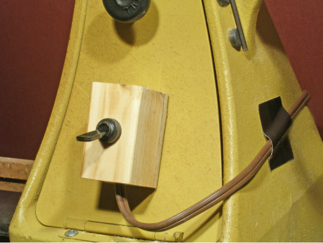 Apply one version (hook
or loop) to the back of the switch enclosure. Place swatches of the other version
on the lathe or anywhere else you may want to place the switch. The only disadvantage
of this method is that it requires a swatch of Velcro at every point you might wish
to stick the switch.
Apply one version (hook
or loop) to the back of the switch enclosure. Place swatches of the other version
on the lathe or anywhere else you may want to place the switch. The only disadvantage
of this method is that it requires a swatch of Velcro at every point you might wish
to stick the switch.
If you can live with a semi-
My preference, as I have said, is to go with a fixed location for the switch and “nail it to the wall,” so to speak.
A Movable Bracket
A bracket that fits into the gap between the ways of the lathe can be used to put the switch almost at your fingertips. The suitability of this method depends a lot on the type of turning you do and whether you need to pull the tailstock all the way back to the end of the lathe.
The bracket can be switched to the headstock side of the tailstock simply by picking it up and moving it over. I think it would be handy for a person who does a lot of spindle turning.


Support Attached to the Lathe
The bolt holes in the legs of the lathe provide yet another optio n for mounting the
remote switch. It is shown in the diagram at right.
n for mounting the
remote switch. It is shown in the diagram at right.
This method allows the tailstock to be removed, but obviously cannot be used on a
lathe with a swing-
Wall Attachment
If your lathe is located near a wall, you may consider mounting the switch on a bracket
that mounts on the wall. One design t hat is quick and easy to build is shown in
the diagram at right.
hat is quick and easy to build is shown in
the diagram at right.
You will realize that it’s possible to eliminate the vertical strip that fits flat against the wall and attach everything directly to the wall. I prefer having the vertical strip because it simplifies the installation, and if you ever want to move it, all you have to deal with is two screws.
Variations on a Theme
There are countless variations on the methods I’ve illustrated just to give you an
idea of the possibilities. What I’ve not considered is a fixture that hangs down
from the ceiling, or one that is free-
And, of course, if you go with one method and it doesn’t work out, you can always swap it for a different method.