

A Three-
A project.
This display stand is ideal for a variety of items ranging from spices to jewelry
to miniature collectibles. Or if you just happen to be a woodturner who makes bottle
stoppers or other small items, it will work for that as well. A lazy Susan in the
base allows it to rotate for easy access to any part of it, and it can be disassembled
for easy storage. What’s not to like about this?
rotate for easy access to any part of it, and it can be disassembled
for easy storage. What’s not to like about this?
This article describes, step-
A Brief Description
The lazy Susan mechanism is installed between the base and the bottom tray to make
a permanent assembly. The machine-


A tenon at the top of the lower support engages a matching recess on the bottom of the middle tray. The hanger bolt of the upper support engages a nut embedded in the tenon of the lower support. This secures the middle tray and anchors the upper support.
In a similar manner, the top tray is installed on the upper support, held on by the hanger bolt installed in the finial.
Dimensions
The diameters I chose for the three trays are 10”, 8”, and 6”. The diameter of the
base is 9”. The separation between the trays is 3.5”. The height of the handle is
3”. Blanks were glued up using 3/4” kiln-
You can change the diameters of the trays as you see fit. I think a 6” lazy Susan
will work fine for trays up to 18” in diameter. If you want to go smaller, you can
purchase lazy Susan mechanisms 3” square, maybe even smaller if you search around.

The spacing between the trays and overall height can be adjusted by making the central supports taller or shorter. And, of course, the number of trays can be more than three. The photo at right shows three variations that serve as displays in a chocolate shop in New York City. The larger one is the exact same one as shown at the beginning of this article.
Base and Bottom Tray
The top of the base and the bottom of the tray must be shaped to accommodate the lazy Susan. A recess in the top of the base and one on the underside of the bottom tray narrows the gap between the two so the lazy Susan is mostly hidden in the final assembly.
It is important for the lazy Susan to be centered on the bottom tray so that no wobble is evident when the unit rotates. These requirements lengthen the turning process, but overall it’s a straightforward matter of doing a series of fairly easy tasks.
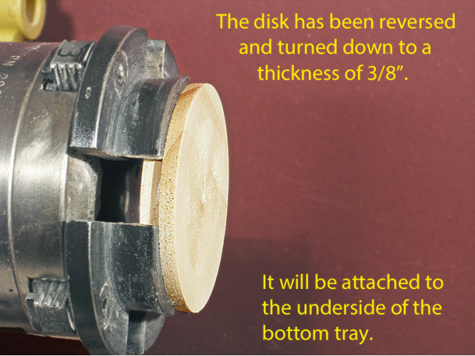
I think the easiest way to center the lazy Susan on the bottom of the tray is to form a tenon and then simply place the lazy Susan around the tenon. A small disk (like a waste block) is attached to provide extra thickness for forming the tenon. This is not all wasted effort because the disk also provides a means of mounting the blank in a scroll chuck.
When you go to put the pieces together you will discover that there is no way to screw the lazy Susan to the base, turn it over, and then screw the other side to the bottom of the tray – the base gets in the way! This problem, however, is easily solved by drilling an access hole through the base so that the screws can be installed by working through the hole. The hole remains in the finished piece: a maker’s mark, of sorts.
Here is a step-
Make the bottom tray.

0. In anticipation of Step 2 below, prepare a disk about 3/8” thick with a diameter slightly larger than the opening in the middle of the lazy Susan. This will become the tenon that centers the lazy Susan.

1. Beginning with a rough- jam the side that
will become the bottom against a flat surface. Form an inset tenon no deeper than
7/32” on the face that will become the top of the tray.
jam the side that
will become the bottom against a flat surface. Form an inset tenon no deeper than
7/32” on the face that will become the top of the tray.
2. Reverse the blank in a scroll chuck. Clean up the surface if necessary and true up the edge. Flatten the surface as required and attach the disk you prepared in Step 0 above. Allow the glue to cure.

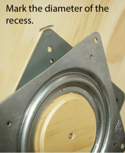
3. Pull the tailstock back and true up the edge of the disk attached in Step 2 above. Reduce its diameter until the lazy Susan will just slide over it. Also, check to see that the tenon (from Step 0) runs true; true it up if it does not. Mark a circle that outlines the circumference of the recess for the lazy Susan.


4. Use a parting tool to cut grooves to serve as depth indicators when hollowing the recess. Hollow the recess to a depth of 1/8” relative to the bottom of the tray. Test the fit of the lazy Susan in the recess.


5. Reverse the blank in the scroll chuck. Hollow the top surface to a depth of about 1/4” in order to create a lip at the edge. Use a sanding block to flatten the surface. Shape the rim and the edge of the tray. Remove the tray from the lathe.


6. Apply double-


Note: you can use a different chucking method for this step. Cole jaws are good if you have a set that is large enough to grip the blank. A vacuum chuck can be used as well, but you will then have to perform the next step, drilling the holes, off the lathe, perhaps using a drill press.
7. Drill a 3/8” hole about 1/4” deep at the center of the disk. This hole will capture
the head of  the hex nut used to hold the lower vertical support in place. Then use
a 7/32” bit to drill a hole the rest of the way through the tray.
the hex nut used to hold the lower vertical support in place. Then use
a 7/32” bit to drill a hole the rest of the way through the tray.
8. Gently remove the tray from the flat surface. Maintain a light pressure against the tray for a fraction of a minute and it should release. Clean up any residue from the tape with lacquer thinner. This completes the bottom tray.
Make the base.
A bit of hollowing is required on both the top and bottom of the base. The lazy Susan
seats in a shallow recess in the top. The bottom of the base is hollowed in the usual
manner to shape the foot.
shallow recess in the top. The bottom of the base is hollowed in the usual
manner to shape the foot.
1. Jam the blank against a flat surface with what will become the bottom adjacent to the tailstock. Cut an inset tenon to a depth of not more than 1/4”. (This is like Step 1 in making the bottom tray.)
2. Mount the blank in a scroll chuck using the newly-


3. Examine the lazy Susan mechanism and decide which side is to be the top and which is to be the bottom. Select as the TOP the side where the metal is continuous through the center hole. Label the sides “top” and “bottom.”
Note: I made a significant error when putting this together. Thinking it made no difference which was taken to be the top, I selected the top to be the side with the seam in the metal near the center hole, which is to say that the ID of the lazy Susan is attached to the base which does not rotate.
Upon assembly, I found the tray would not rotate smoothly on the base. It was binding in some manner. The centering tenon on the tray was rubbing against the ID of the lazy Susan mechanism.
I discovered the error after I had made the photographs. Therefore, the orientation of the lazy Susan mechanism in the photos is upside down from what it should be. However, the discrepancy is not apparent unless you examine the photos closely. Go with the labels and ignore the details of the photo. The following photos show how to properly select the top and bottom sides.


4. Temporarily place the lazy Susan top-


Double check: did you get that part about “top-
5. Jam the top of the base (the inside of the recess) against a flat surface using
double-


Shape the foot, and then begin hollowing closer to the center. At the diameter where the screws will be driven into the base, hollow no deeper than 1/8” in order to leave sufficient thickness for the screws. The rest can be hollowed to 1/4” or slightly more to remove the inset tenon. The base is now complete.
Assemble the Base, Lazy Susan, and Bottom Tray.

It is easier to apply a finish to the base and bottom tray before they are joined together. However, you can go ahead and put them together unfinished and then remove the tray (four small screws) when you are ready to apply the finish.
1. A 10 - acer if needed,
through the hole. Start the nut on this screw and then position the nut over the
3/8” hole. Tighten the bolt until the nut seats on the bottom. If you think it’s
necessary, apply a bit of epoxy or medium CA glue around the nut.
acer if needed,
through the hole. Start the nut on this screw and then position the nut over the
3/8” hole. Tighten the bolt until the nut seats on the bottom. If you think it’s
necessary, apply a bit of epoxy or medium CA glue around the nut.
2. Position the lazy Susan, top side up, in the recess on the base. Do not cover up the access hole. Be sure the access hole lines up with the holes in the top flange. Drill pilot holes and then install the screws.
 3. With the tray upside down on a flat surface, position the base and lazy Susan
over the tray. The tenon on the tray should make this easy to do. Working through
the access hole, mark the locations where pilot holes should be drilled. Remove the
base and drill the holes.
3. With the tray upside down on a flat surface, position the base and lazy Susan
over the tray. The tenon on the tray should make this easy to do. Working through
the access hole, mark the locations where pilot holes should be drilled. Remove the
base and drill the holes.

4. Finally, place the base back over the tray and install the screws.


